Network Routing
Simple Networking Routing and Routers
This section will explain routing in simple terms with some simple standard rules. There may be exceptions to these rules, but for introductory purposes we will keep the first example simple. Please be aware, that the examples in this section are working examples, but more complexity may be added when a larger network is
considered, and multiple data routes become available.
Each network interface card (NIC) has a specific address which is an IP address or number. When data is sent between two computers, the data must be sent in a package that has the address of the intended receiver (IP) on it. It is like an envelope (ethernet) with the sender’s and recipient’s address on it. There is somewhat of a difference, however. When the computer intends to send a packet, it first checks its routing table to see if the intended data must be sent through a gateway. Many computers only have a simple routing table, which is built from the network mask and the gateway information entered, when you set your computer up to do networking. The computer, when set up for networking, must be assigned an IP address, netmask, and default gateway. This may be done manually or done automatically using Dynamic Host Configuration Protocol (DHCP) to assign this information to the computer when it boots. DCHP is described in another section. If the computer determines that the packet must be sent to a gateway, it puts it in a special packet (ethernet) for that gateway, with the actual recipient’s address wrapped inside.
In the above paragraph, data packets are equated to a letter with an envelope. For this type of thinking, the envelope would be similar to the ethernet, SLIP, or PPP packet which encapsulates the IP packet. The IP packet and its encapsulated data would similar to a letter. Here’s generally what happens when a package is sent:
The sending computer checks the IP part of the package to see the sender’s IP address, and based on the address and instructions in its routing table will do one of the following:
1. Send the packet to the ethernet address of the intended recipient. The following will happen:
1. The ethernet card on the receiving computer will accept the packet.
2. The other network levels (IP, TCP) will open the packet and use it ccording to filtering and other programming instructions.
2. Send the packet to the ethernet address of a router, depending on the instructions in the routing table.
1. The ethernet card on the router will accept the packet.
2. The IP level of the router will look at the packet’s IP address and determine according to its routingtable where to send the packet next. It should send it to another router or to the actual recipient.
3. The router will encapsulate the IP packet in another ethernet packet with the ethernet address of the next router or the intended recipient.
4. Router hops will continue until the packet is sent on a network where the intended recipient is physically located unless the packet expires.
5. The ethernet card on the receiving computer will accept the packet.
6. The other network levels (IP, TCP) will open the packet and use it according to filtering and other programming instructions.
Lets say you enter an IP address of 10.1.20.45 and a netmask of 255.255.0.0. This means you are on the network 10.1.0.0 (I show it as 10.1.x.x, the X’s mean don’t care conditions). The machine’s IP address and netmask, together define the network, that it’s NIC is on. Therefore any machine that fits in the address range provided under 10.1.x.x can be accessed directly from your NIC, and any that are not in this number range, such as 10.3.34.67 cannot be accessed directly and must be sent to a gateway machine since it is on another network. Typically most machines will use their netmask to make this determination which means if the address does not match their known network, the package will be sent to that machine’s default gateway in a special package meant for a router. It works similar to a post office. When you send a letter in your town, you put it in the local slot. It can be delivered to someone else in your town (network), but if you are sending to another town (network), you put the letter in the out of town slot (default gateway), then the mail personnel put it in a special container or box and send it to a main town (gateway), which then decides where to send it based on its address. Although this simple network and default gateway may be common, specific computers or gateways can have much more complex rules for routing that allow exceptions to this example.
Please be aware that in order to be forwarded, data packets must be addressed to a router. They cannot just be sent to the recipient’s address out to a network. The router does not pick packets off the network and forward them. If a packet is sent on a network and a valid recipient is not on that network, there will be no response. This will be demonstrated in the next section where a subnetwork will be described.
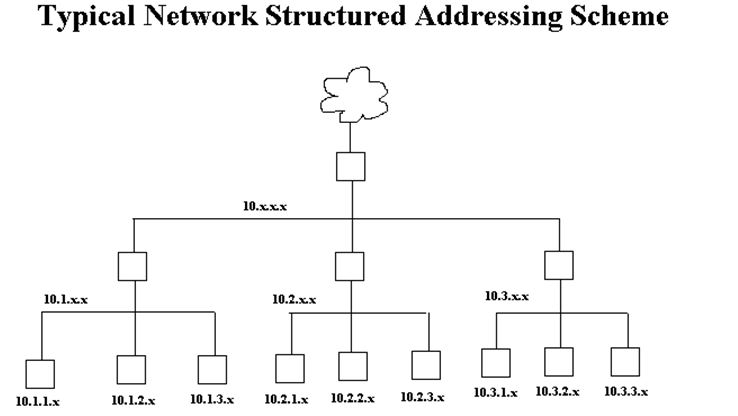
To keep routing simple, most networks are structured as shown below. Generally, the higher networks are 10.x.x.x, then the next are 10.0-254.x.x, then 10.0-254.0-254.x. The number 10 is used as an example Class A network. This numbering scheme keeps routing simple and is the least confusing but networks can be set up in other ways. In the diagram below, only gateways and their networks are shown.
Network Routing
In my simple network example below I vary from convention and make network 192.168.2.x be below network 192.168.1.x. causing traffic between the internet and 192.168.2.x to go through the network 192.168.1.x. Normally the network 192.168.1.x would be 192.168.x.x, but this will show you that there can be many variants that will work as long as you have thought your layout through well, and set your routing tables up in your gateways correctly.
Network Routing
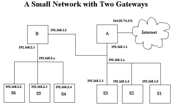
The boxes labeled A and B must be gateways or routers in order for anyone on networks 192.168.2.x or 192.168.1.x to talk to any other network or internet. The boxes labeled S1 through S6 are stations which could be workstations or servers providing services like BOOTP, DHCP, DNS, HTTP, and/or file sharing such as NFS or Samba. The gateways may also provide these services. These stations may combine any combination of server or workstation function. The reasons for putting the various services on separate machines is because of security concerns and the ability of a given machine to handle specific demand. Typically, the computer that is connected directly to the internet, would be a firewall and provide no other services for security reasons. For example, it is not a good idea to provide TFTP services on a machine that you want to have high security. This is why, depending on the security needs of the company or individual along with the relative amount of each service to be provided, various servers are set up with limited functionality.
The machine S6 in the diagram above has the following characteristics:
IP Address: 192.168.2.2
Network: 192.168.2.0
Netmask: 255.255.255.0
Gateway: 192.168.2.1
In Linux, the “ifconfig” command is used to configure the NIC and the command “route” is used to set up routing tables for that machine. Please note that in Redhat Linux, the GUI interface programs “netconf” and “linuxconf” may be used to set this up also. These GUI interface programs will set these changes up to be permanent by writing them to files that are used to configure network information. Changes made with “route” without adding the changes to permanent files will no longer be valid when you reboot the machine. The command “ifconfig eth0 192.168.2.2 netmask 255.255.255.0” will set the NIC card up with its address and network number. You can type “netconfig”, then select “basic host information” and do the same thing. The command “route add -net default gw 192.168.2.1 dev eth0” will add the route required for this computer for its gateway. This can be done using
“ifconf” by selecting “routing and gateways” and “defaults”, then setting the address of the default gateway, and enabling routing. Please be aware that various versions of Linux have different means of storing and retrieving network and routing information and you must use the tools that come with your system or learn it well enough to determine what files to modify. On Redhat 6.1 the file “/etc/sysconfig/static-routes” can be modified to make your route changes permanent, but this does not apply to your default route. Other files are “/etc/sysconfig/routed” and “/etc/sysconfig/network”. Other files include “/etc/gateways”, “/etc/networks”, “/proc/net/route”, “/proc/net/rt_cache”, and “/proc/net/ipv6_route”. The file “/etc/sysconfig/network-scripts” is a script file that
controls the network setup when the system is booted.
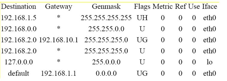
If you type “route” for this machine, the routing table below will be displayed:
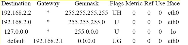
Here is a simple explanation of routing tables and their purpose. All computers that are networked have a routing table in one form or another. A routing table is a simple set of rules that tell what will be done with network packets. In programming language it is easiest to think of it as a set of instructions, very similar to a case statement which has a “default” at its end. If can also be thought of as a series of if..then..elseif..then..else statements. If the lines above are labeled A through C and a default (the last line), an appropriate case statement is: (Don’t count the header line)
switch(address){
case A: send to me;break;
case B: send to my network;break;
case C: send to my local interface;break;
default: send to gateway 192.168.2.1
An appropriate if statement is:
if (address=me) then send to me;
elseif (address=my network) then send to my network;
elseif (address=my local) then send to my local nterface;
else send to my gateway 192.168.2.1;
In everyday terms this is similar to a basic decision process. Imagine you are holding a letter. If it is addressed to you, you keep it, if it is addressed to someone in your town, you drop it in the local slot at the post office, but if it is addressed to someone out of town, you would drop it in the out of town slot.
Note how the routing table is arranged. It is arranged from the most specific to the least specific. Therefore as you go down the table, more possibilities are covered. You will notice the first Genmask is 255.255.255.255 and the last is 0.0.0.0. There can be no doubt that the last line is the default. The genmasks between the start and the end have a decreasing number of least significant bits set.
The above default routing table may be added manually with the command:
route add -net default gw 192.168.2.1 dev eth0
The routing table for machine B, the gateway for the network 192.168.2.0 is as follows.

The Iface specifies the card where packets for this route will be sent. The address of eth1 is 192.168.1.2 and eth0 is 192.168.2.1. The NIC card addresses could have easily been switched. Line 1 (above) provides for the eth0 address, while line 2 provides for the address of eth1. Lines 3 and 4 are the rules for traffic going from network 192.168.1.0 to network 192.168.2.0 which will be sent out on NIC eth0. Lines 5 and 6 are the rules for traffic going from network 192.168.2.0 to network 192.168.1.0 which will be sent out NIC eth1. This may seem confusing, but please note the first value on lines 3 and 4 is 192.168.2.0 which the header indicates as the
destination of the packet. Don’t think of it as source! The last line is the default line which specifies that any packet not on one of the networks 192.168.1.0 or 192.168.2.0 will be sent to the gateway 192.168.1.1. This is how the internet access can be attained, though IP masquerading will probably be used. The flags above mean the following:
- U – Route is up
- H – Target is a host
- G – Use gateway
There are other flags, you can look up by typing “man route”. Also the metric value above, indicating the distance to the target, is not used by current Linux kernels but may be needed by some routing daemons. Please note that if route knows the name of the gateway machine, it may list its name rather than the IP address. The same is true for defined networks. Networks may be defined in the file “/etc/networks” as in the example:
net1 192.168.1.0
net2 192.168.2.0
The routing table above can be set up with the following commands.
route add -net 192.168.2.0 netmask 255.255.255.0 gw 192.168.2.1 dev eth0
route add -net 192.168.1.0 netmask 255.255.255.0 gw 192.168.1.2 dev eth1
Again be aware that you are specifying destination networks here and the ethernet device and address the data is to be sent on.
In Redhat Linux this can be specified using “netconf” by selecting “routing and gateways” and “other routes to networks” and entering the following:
Network Netmask Gateway
192.168.2.0 255.255.255.0 192.168.2.1
192.168.1.0 255.255.255.0 192.168.1.2
Alternatively in Redhat Linux, you can add the following two lines to the file “/etc/sysconfig/static-routes”:
eth0 net 192.168.2.0 netmask 255.255.255.0 gw 192.168.2.1
eth1 net 192.168.1.0 netmask 255.255.255.0 gw 192.168.1.2
The commands to delete the above routes with route are:
route del -net 192.168.2.0 netmask 255.255.255.0 gw 192.168.2.1 dev eth0 route del -net 192.168.1.0 netmask 255.255.255.0 gw 192.168.1.2 dev eth1
Be aware, the program route is very particular on how the commands are entered. Even though it may seem that you entered them as the man page specifies, it will not always accept the commands. I don’t know if this is a bug or not, but if you enter them as described here with the network, netmask, gateway, and device specified, it should work. The slightest misnomer in network name, netmask, gateway, device, or command syntax and the effort will fail.
More Complex Networking Routing
Now let’s modify the small network in the example in the previous section. The 192.168.1.x network is changed to 192.168.x.x and gateway B’s address is changed to 192.168.10.1. All the netmasks on the computers on the 192.168.x.x network are modified to 255.255.0.0 to accommodate the change, except machine S3 which keeps the netmask 255.255.255.0 and changes its address to 192.168.10.3. This effectively puts S3 on a different network than S2 and S1, it no longer believes it can talk directly to them and must talk to gateway B to talk to them. It can’t even talk to gateway A anymore since it can’t address it directly. Machines S1, S2, and A are not on network 192.168.10.0, their addresses are 192.168.1.*. S1 and S2 can talk to S3, but S3 will not be able to respond unless it utilizes gateway B.
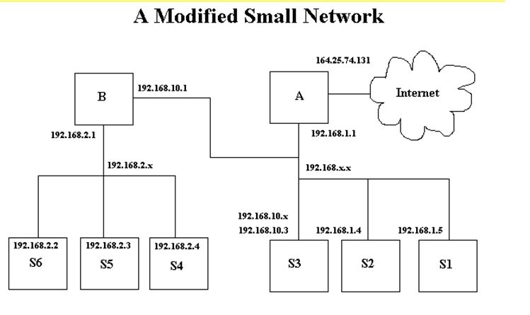
Please be aware, in the example in the previous section, that gateway A was aware of gateway B. If it were not, no messages could have been transmitted from the internet to the 192.168.2.0 network. In this example, gateway A knows nothing about gateway B, and as far as it’s concerned, the network 192,168.2.0 is part of 192.168.0.0 and there is no gateway between them. Gateway B, does know about gateway A and is using that gateway as its default gateway. Therefore if S1 and S2 use gateway A for their default gateway, they will not be able to talk to S4, 5, or 6 unless their routing table is modified. S1 and S2 will be able to talk to S3, however, assuming S3 is using gateway B.
Here is a listing of machine S1’s routing table, using gateway A as default and no other routes.
Destination Gateway Genmask Flags Metric Ref Use Iface
192.168.1.5 * 255.255.255.255 UH 0 0 0 eth0
192.168.0.0 * 255.255.0.0 U 0 0 0 eth0
127.0.0.0 * 255.0.0.0 U 0 0 0 lo
Default 192.168.1.1 0.0.0.0 UG 0 0 0 eth0
Here it is modified to let it use network 192.168.2.0.
It specifies the gateway B, 192,168.10.1 to be used if the destination is 192.168.2.x.
The figure below shows an ethernet network with bus topology excluding the hubs. It is a large Class A network with many subnetworks. The machines labeled A through D are routers or potential routers and each have two network interface cards(NIC). These machines may be called gateways since their function is to be a gate to another location. Each card has a valid address on its own network or subnetwork. The table below lists each gateway, and each NIC address and associated network.


In this figure, there are 9 gateways. which are labeled A through I. There are multiple paths between several networks. The possible paths between networks 10.1.100.x and 192.168.1.x can be through gateways E, D, C, then G (E-D-C-G) or through gateways H-I. The path from 10.3.100.x ot 10.1.20.x can be E-D-B-F or H-I-G-C-BF. Obviously there are ways to set the routing paths up that may not be fully efficient. In this type of network, the administrator must give careful thought to the setup of the routing tables in their gateways. It would be easy to set up an infinite packet route loop in this network where some packets may go in circles from router to router. Here’s how I would route for this network.
The below table lists each network and their default router.
Network Default Router
10.3.100.x E
10.3.150.x H
192.168.1.x G
10.1.20.x F
10.1.x.x B
10.2.x.x C
10.3.x.x D
10.x.x.x A
The router, I, is not used as a default router for any network.
The table below lists an abbreviated route table for each gateway.
Router Destination Gateway
A 192.168.1.x C
10.1.x.x B
10.2.x.x C
10.3.x.x D
10.x.x.x 10.0.0.1
default internet
B 10.1.20.x F
10.1.x.x 10.1.0.1
Default A
C 192.168.1.x G
10.2.x.x 10.2.0.1
default A
D 10.3.150.x E
10.3.100.x E
10.3.x.x 10.3.0.1
default A
E 192.168.1.x * H
10.3.150.x H
10.3.100.x 10.3.100.1
default D
F 10.1.20.x 10.1.20.1
default B
G 10.3.100.x * I
192.168.1.x 192.168.1.1
10.3.150.x * I
default C
H 192.168.1.x I
10.3.100.x 10.3.100.2
10.3.150.x 10.3.150.1
default E
I 10.3.100.x H
192.168.1.x 192.168.1.2
10.3.150.x 10.3.150.2
default G
The destinations with ‘*’ indicate destinations that shorten the normal route path through network 10.3.150.x.
Also in this network since there are multiple possible paths, dynamic routing can be used to provide alternate routing, if one router goes down.
IP Masquerading
IP masquerading is a form of network address translation (NAT) which allows internal computers with no known address outside their network, to communicate to the outside. It allows one machine to act on behalf of other machines. It’s similar to someone buying stocks through a broker (without considering the monetary transaction). The person buying stocks, tells the broker to buy the stocks, the broker gets the stocks and passes them to the person who made the purchase. The broker acts on behalf of the stock purchaser as though he was the one buying the stock. No one who sold the stock knew or cared about whether the broker was buying for himself or someone else.
Please DO NOT confuse routers with firewalls and the performance of IP masquerading. The commands that allow IP masquerading are a simple form of a firewall, however routing is a completely different function, as described previously. Setting a computer up to act as a router is completely different than setting up a computer to act as a firewall. Although the two functions are similar in that the router or firewall will act as a communication mechanism between two networks or subnets, the similarity ends there. A computer can be either a router or a firewall, but not both. If you set up a computer to act as both a router and a firewall, you have defeated the purpose of your firewall!
If you refer to the diagram below, the machines on network 192.168.2.x will obtain services through gateway B using IP masquerading, when gateway B is setup properly. What basically happens when IP masquerading is set up on gateway B is described in the following example. If machine S6 tries to ping S2, its ping packages will be wrapped in a package for its default gateway, gateway B, because S6 knows by its netmask that S2 in on another network. When gateway B receives the packages from S6, it converts them to ping packages as though they were sent from itself and sends them to S2. As far as S2 can tell, gateway B has pinged it. S2 receives the packages and responds to gateway B. Gateway B then converts the packages to be addressed to S6 and sends them. This is why it is called IP masquerading, since gateway B masquerades for machines S4, S5, and S6. Machines S1 through S3 and gateway A cannot initiate any communication with S4 through S6. In fact they have no way to know that those machines even exist!
